
This service manual was written expressly or authorized Toro dealer service technicians. The Toro Company has made every effort to make the information in this manual complete and correct.
Basic Shop safety knowledge and mechanical/electrical skills are assumed. The Table of COntents lists the systems and the related topics covered in this manual.
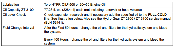
For service information on dirve systems, please refer to Hydro-Gear ZT-2800/ZT-3100/ZT-3400 service manual (BLN 52441). For information specific to the engines used on this unit, refer to the appropriate engine manufacturer's service and repair instructions.
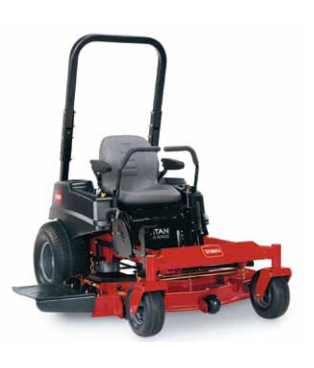
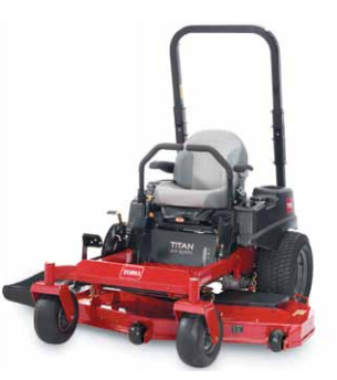
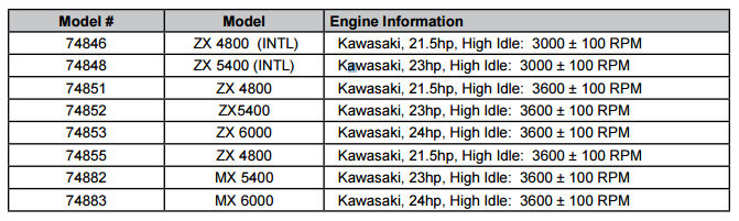
TITAN model year 2014 is covered in this manual. The manual may also be specified for use on later model products.
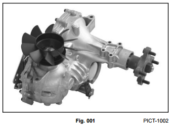
The hydrostatic transaxle is a sophistocated component. Maintain strict cleanliness control during all stages or service and repair. Cover or cap all hose ends and fittings whenever they are exposed. Even a small amount of dirt or other contamination can severely damage the system.
If you have any questions or comments regarding this manual, please contact us at the following address:
The Toro Company reserves the right to change product specifications or this manual without notice.

This symbol means WARNING or PERSONAL SAFETY INSTRUCTION read the instruction because it has to do with your safety/ Failure to comply with the instruction may result in personal injury or even death.
This manual is intended as a service and repair manual only. The safety instructions provided herein are for troubleshooting, service, and repair or the TITAN zero turn mowers.
The TITAN operator's manuals contain safety information and operating tips for safe operating practices. Operator's manuals are available online through your Toro pasts source or:
Always turn off the engine and disconnect the spark plug wire(s) before cleaning, adjusting, or repair.
Stay clear of all moving parts whenever the engine is running. Treat all normally moving parts as if they were moving whenever the engine is running or has the potential to start.
Do not touch the engine, muffler, or other components, which many increase in temperature during operation, while the unit is running or shortly after it has been running.
Avoid spilling fuel and never smoke while working with any type of fuel or lubricant. Wipe up any spilled fuel or oil immediately. Never remove the fuel cap or add fuel when the engine is running. Always use approved, labeled containers for storing or transporting fuel and lubricants.
Never operate an engine in a confined area without proper ventilation.
Battery acid is poisonous and can cause burns. Avoid contact with skin, eyes and clothing. Battery gases can explode. Keep cigarettes, sparks and flames away from the battery.
Use only original equipment parts to ensure that important safety criteria are met.
Always clear the area of bystanders before starting or testing powered equipment.
Always clear the area of bystanders before starting or testing powered equipment.
Never alter or modify any part unless it is a factory approved procedure.
Always test the safety interlock system after making adjustments or repairs on the machine. Refer to the Electrical section in this manual for more information.
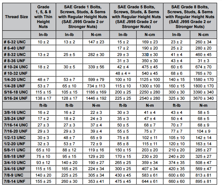
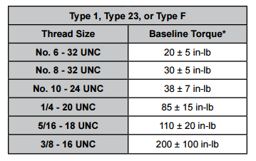
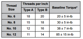
Table of ContentsRecommended fastener torque values are listed in the following tabels. For critical applications, as determined by Toro, either the recommended torque or a torque that is unique to the application is clearly identified and specified in the service manual.
These torque specifications for installation and tightening of fasteners shall apply to all fasteners which do not have a specific requirement identified in the service manual. The following factors shall be considered when applying torque: cleanliness of the fastener, use of thread sealant (e.g. Loctite(R)), degree of lubrication on the fastener, presence of a prevailing torque feature, hardness of the surface underneath of the fastener's head, or similar condition which affects the installation.
As noted in the following tables, torque values should be reduced by 25% for lubricated fasteners to achieve the similar stress as a dry fastener. Torque values may also have to be reduced when the fastener is threaded into aluminum or brass. The specific torque value should be determined based on the aluminum or brass material stength, fastener size, length of thread engagement, etc.
The standard method of verifying torque shall be performed by marking a line on the fastener (head or nut) and mating part, then back off fastener 1/4 of a turn. Measure the torque required to tighten the fastener until the lines match up.
Note: Reduce torque values listed in the table above by 25% for lubricated fasteners. Lubricated fasteners are defined as threads coated with a lubricated such as oil, graphite, or thread sealant such as Loctite (R).
Note: Torque values may have to be reduced when installing fasteners into threaded aluminum or brass. The specific torque value should be determined based on the fastener size, the aluminum or base material strength, length of thread engagement, etc.
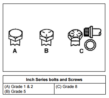
Note: The nominal torque values listed above for Grade 5 and 8 fasteners are based on 75% of the minimum proof load specified in SAE J429. The tolerance is approximately +/- 10% of the nominal torque value. Thin height nuts include jame nuts.
Note: Reduce torque values listed in the table above by 25% for lubricated fasteners. Lubricated fasteners are defined as threads coated with a lubricant such as oil, graphite, or thread sealant such as Loctite (R).
Note: Torque values may have to be reduced when installing fasteners into threaded aluminum or brass. The specific torque value should be determined based on the fastener size, the aluminum or base material strength, length of thread engagement, etc.
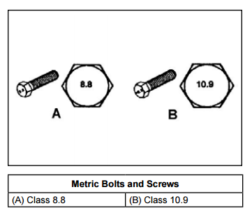
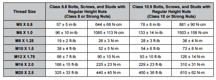
Note: The nominal torque values listed above are based on 75% of the minimum proof load specified in SAE J1199. The tolerance is approximately +/- 10% of the nominal torque value. Thin height nuts include jam nuts.
| Thread Size | Class 8.8 Bolts, Screws, and Studs with Regular Height Nuts (Class 8 or Strong Nuts) | Class 10.9 Bolts, Screws, and Studs with Regular Height Nuts (Class 10 or Strong Nuts) | ||
|---|---|---|---|---|
| M5 X 0.8 | 57 +/- 5 in-lb | 644 +/- 68 Ncm | 78 +/- 8 in-lb | 881 +/- 90 Ncm |
| M6 x 1.0 | 96 +/- 2 ft-lb | 1085 +/- 113 Ncm | 133 +/- 14 in-lb | 1503 +/- 158 Ncm |
| M8 X 1.25 | 19 +/- 2 ft-lb | 26 +/- 3 Ncm | 28 +/- 3 ft-lb | 38 +/- 4 Nm |
| M10 X 1.5 | 38 +/- 4 ft-lb | 52 +/- 5 Nm | 54 +/- 6 ft-lb | 73 +/- 8 Nm |
| M12 X 1.75 | 66 +/- 7 ft-lb | 90 +/- 10 Nm | 93 +/- 10 ft-lb | 126 +/- 14 Nm |
| M16 X 2.0 | 166 +/- 15 ft-lb | 225 +/- 23 Nm | td>229 +/- ft-lb | 310 +/- 31 Nm |
| M20 X 2.5 | 325 +/- 33 ft-lb | 440 +/- 45 Nm | 450 +/- 36 ft-lb | 610 +/- 62 Nm |
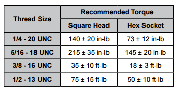
| SAE Grade 8 Steel Set Screws | ||
|---|---|---|
| Thread Size | Recommended Torque | |
| Square Head | Hex Socket | |
| 1/4 - 20 UNC | 140 +/- 20 in-lb | 73 +/- 12 in-lb |
| 5/16 - 18 UNC | 215 +/- 35 in-lb | 145 +/- 20 in-lb |
| 3/8 - 16 UNC | 35 +/- 10 ft-lb | 18 +/- 3 ft-ln |
| 1/2 - 12 UNC | 75 +/- 15 ft-lb | 50 +/- 10 ft-lb |
*Hoe size, material strength, material thickness and finish must be considered when determining specific torque values. All torque values are based on nonlubricatedfasteners.
Conversion Factors
in-lb X 11.2985 = N-cm
ft-lb X 1.3558 = N-m
Conversion Factors
N-cm X -0.08851 = in-lb
N-cm X 0.73776 = ft-lb
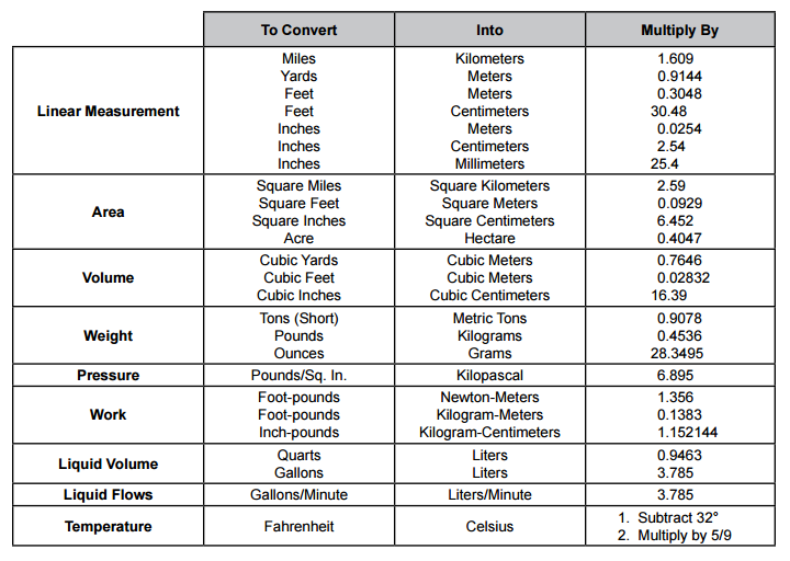
 Table of Contents
 Table of Contents
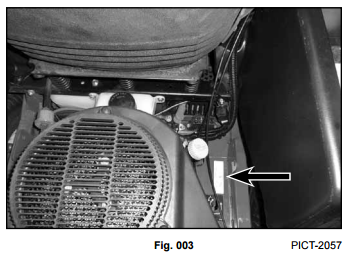
The model and serial number identification plate is located on the frame, near the engine, on the RH side of the unit (Fig. 003)
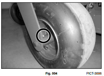
Grease Type - No. 2 general=purpose litium base grease.
A grease fitting is located on each of the front wheel hubs.
The front wheel hubs should be greased every 25 hrs. (Fig. 004).
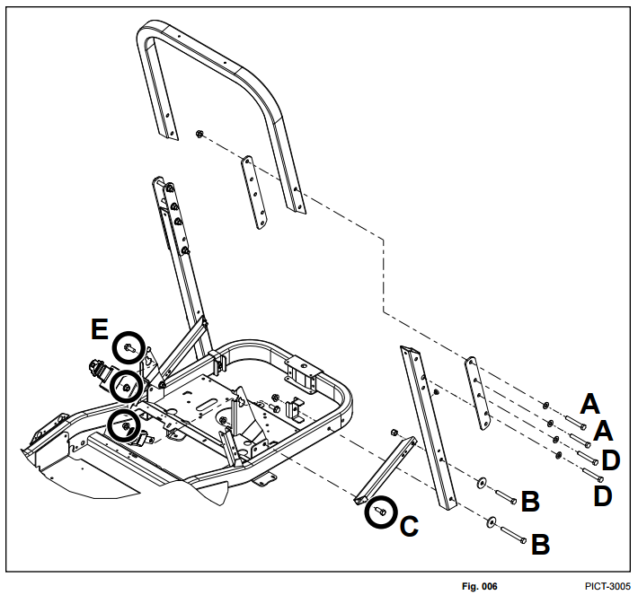
E. Seat Belt Mounting Fasteners - 75 ft-lbs. (101 Nm)
Table of Contents
 Table of Contents
 Table of Contents